
- #Dia er diagram tool how to
- #Dia er diagram tool full
- #Dia er diagram tool software
- #Dia er diagram tool download
- #Dia er diagram tool windows
Are you trying to present an overall system architecture that involves the definition of business objects? Or are you developing an ER model ready for database creation? You must be clear about the purpose to develop an ER diagram at the right level of detail (Read the section Conceptual, Logical and Physical Data Models for more details)
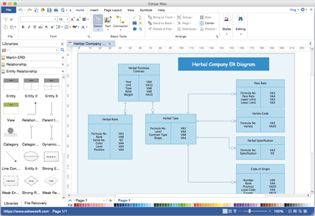
Make sure you are clear about the purpose of drawing the ERD. Try to follow the steps below to understand how to draw an ER diagram effectively. In this section, we will give you some ERD tips. If you find it difficult to get started with drawing an ER diagram, don't worry. The ERD example below shows an example of an ER entity. In ER models, an entity is shown as a rounded rectangle, with its name on top and its attributes listed in the body of the entity shape. When determining entities, think of them as nouns. Transaction) (note: In ERD, the term "entity" is often used instead of "table", but they are the same).


EntityĪn ERD entity is a definable thing or concept within a system, such as a person/role (e.g. In this section, we will go through the ERD symbols in detail. Such an initial model can also be evolved into a physical database model that aids the creation of a relational database, or aids in the creation of process maps and data flow modes.Īn ER Diagram contains entities, attributes, and relationships.
Aid in requirements gathering - Determine the requirements of an information system by drawing a conceptual ERD that depicts the high-level business objects of the system. So, with this ER Diagram tool, your ER design is no longer just a static diagram but a mirror that reflects truly the physical database structure. Database creation and patching - Visual Paradigm, an ERD tool, supports a database generation tool that can automate the database creation and patching process by means of ER diagrams. All these allow you to analyze an existing database and to reveal database problems easier. You can easily locate entities, view their attributes and identify the relationships they have with others. By visualizing a database schema with an ERD, you have a full picture of the entire database schema.
Database debugging - To debug database issues can be challenging, especially when the database contains many tables, which require writing complex SQL in getting the information you need. By drawing ER diagrams to visualize database design ideas, you have a chance to identify the mistakes and design flaws, and to make corrections before executing the changes in the database. To avoid ruining the data in a production database, it is important to plan out the changes carefully. Database design - Depending on the scale of change, it can be risky to alter a database structure directly in a DBMS. So, when do we draw ERDs? While ER models are mostly developed for designing relational databases in terms of concept visualization and in terms of physical database design, there are still other situations when ER diagrams can help. An mechanical engineer may design some Hydraulic or Pneumatic diagrams.In a typical ER design, you can find symbols such as rounded rectangles and connectors (with different styles of their ends) that depict the entities, their attributes, and inter-relationships. An electrical engineer may use Dia to create a diagram to show how a circuit works. A network administrator can create a diagram to model the company's company network. A computer programmer can create a flow chart to show the execution path of a program. A control engineer may draw Cybernetics diagrams. A database designer can represent data relations with ER diagrams. A software developer can create UML diagrams of various types and extend them with the flexibility of a general purpose diagram tool. A requirements engineer can compose e.g. RE-KAOS, RE-Jackson or RE-I* diagrams. A systems engineer can create SADT diagrams for system analysis and design. Features of Dia include multiple-page printing, export to many formats (EPS, SVG, CGM and PNG), and the ability to use custom shapes created by the user as simple XML descriptions. Dia is useful for drawing UML diagrams, network maps, and flowcharts.ĭia can be used by many people in a variety of industries. Its interface and features are loosely patterned after the Windows program Visio. OS X 10.7, OS X 10.8, OS X 10.9, OS X 10.10, OS X 10.11ĭia is an application for creating technical diagrams.
Dia Diagram Editor 0.97.2 Start Download Now


 0 kommentar(er)
